What Is a PLC Control Panel and How Does It Work?

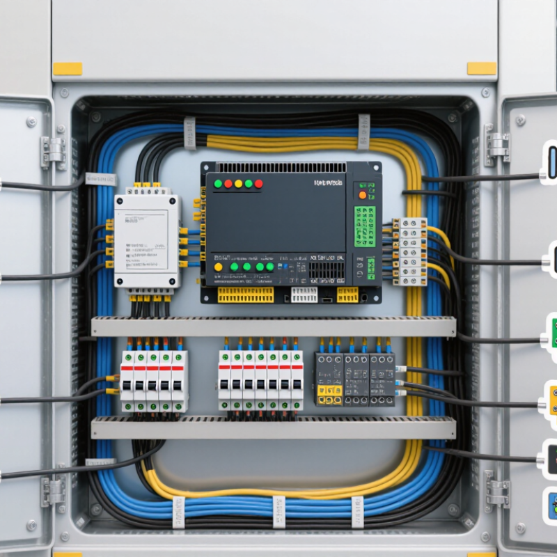
A plc control panel is the practical center of an automated machine. It connects sensors, switches, motors, valves, and safety devices. Inside, you may find a programmable logic controller, power supplies, circuit protection, relays, terminal blocks, and communication modules. Each component has a specific responsibility. Together, they turn electrical signals into controlled mechanical action.

Dick Morley, one of the PLC’s inventors, explained it simply: “The PLC is a computer designed to do control.” That idea remains useful today. A PLC reads input signals, processes programmed instructions, and updates its outputs within a repeating scan cycle. For example, a proximity sensor may detect a metal part. The PLC then checks the logic and energizes a motor starter or pneumatic valve. The sequence can happen in milliseconds.

A well-designed plc control panel also protects people and equipment. Fuses, breakers, grounding, emergency-stop circuits, and suitable enclosures matter. So do clear labels and organized wiring. A loose terminal can stop an entire production line. A poorly separated power cable may create signal noise. Small details become expensive problems.

Modern panels often include HMIs, remote I/O, Ethernet switches, and condition monitoring. These features improve visibility, but they also increase configuration demands. More technology does not automatically mean better control. That assumption deserves reflection. The best design matches the machine, environment, maintenance skills, and safety requirements.

This guide explains how a plc control panel is arranged, how its control cycle works, and how engineers select key components. It also considers practical installation issues that diagrams often overlook. The panel should be understandable, serviceable, and dependable—not merely impressive behind a metal door.
What Is a PLC Control Panel and How Does It Work?

PLC Control Panels: Definition and Core Purpose

What Is a PLC Control Panel and How Does It Work?

PLC Control Panels: Definition and Core Purpose

A PLC control panel is an electrical enclosure that manages machines through programmed logic. It contains a programmable logic controller, power supply, input modules, output modules, and terminal blocks. Circuit protection and cooling components may also be included. The panel receives signals from field devices, such as switches, sensors, and temperature probes. The PLC processes these signals according to its program. It then sends commands to motors, valves, lights, or alarms.

Think of it as the machine’s decision center. A sensor detects a full tank, for example. The PLC reads that condition and stops the filling valve. This action may happen within milliseconds. Clear wiring makes this process dependable. Each terminal should be labeled, secured, and matched with an electrical drawing. During commissioning, technicians often test every input and output individually. Small mistakes can become expensive faults.

The panel’s core purpose is controlled coordination, not merely housing electrical parts. It helps operators monitor processes and adjust machine behavior safely. However, a PLC does not correct poor engineering by itself. A rushed design may work on a test bench but fail in a hot, dusty cabinet. That part deserves more thought. Reliable performance requires suitable components, clean grounding, documented logic, and realistic testing under operating conditions. Regular inspection also reveals loose terminals, damaged insulation, or unusual heat before these issues interrupt production.

Main Components Inside a PLC Control Panel

What Is a PLC Control Panel and How Does It Work?

A PLC control panel is the operating center of an automated machine. Its main components include an enclosure, circuit protection, a power supply, the PLC CPU, input and output modules, terminals, communication interfaces, and an HMI. The PLC reads signals from sensors, processes programmed logic, and sends commands to motors, valves, or alarms. According to the 2024 MarketsandMarkets PLC market analysis, the global market is projected to grow from about USD 11.6 billion in 2023 to USD 16.7 billion by 2028. This growth reflects wider demand for flexible industrial control.

Inside the panel, each component has a practical role. The power supply converts incoming electricity into stable control voltage, commonly 24 VDC. Input modules receive signals from switches and sensors. Output modules activate field devices through relays or transistor circuits. Communication modules connect the PLC with drives, remote I/O, and monitoring systems. During commissioning, a loose terminal can cause more trouble than complex software. A perfect drawing rarely survives the first modification. Clear labels and spare terminals matter.

Tips: Keep power and signal wiring separated. Check heat buildup around the CPU and power supply. Leave spare I/O capacity for future changes. Test every input and output using a written checklist. Record wire numbers, terminal locations, and software revisions. Small omissions become expensive later.

How a PLC Control Panel Processes Signals

A PLC control panel is the working center of an automated machine. It receives field signals, evaluates logic, and sends commands to actuators. The process is fast, but not magical. A sensor may detect a bottle, pressure change, or open guard. Its signal travels through terminal blocks to an input module. Digital inputs often use 24-volt signals, while analog modules commonly read 4–20 mA or 0–10 V ranges.

The controller processes these signals in a repeating scan cycle. It reads inputs, runs the programmed logic, updates outputs, and checks diagnostics. An output module may energize a valve, start a motor starter, or trigger an alarm. The next scan can reveal a changed condition and adjust the response. According to the IEC 61131-3 standard, structured programming methods help engineers organize this control logic. A 2024 MarketsandMarkets report also projects continued growth in industrial control systems, driven partly by connected monitoring and process automation. Growth does not remove mistakes. A neat screen can still hide a loose wire or a poorly scaled sensor.

Tips: Label every wire and channel clearly. Check signal ranges before commissioning. Test normal, fault, and recovery conditions. Keep a record of measured values. A small mismatch can matter. Technicians should compare the PLC diagnosis with real instruments, because software status alone is not proof of field operation.

What Is a PLC Control Panel and How Does It Work? - How a PLC Control Panel Processes Signals

Processing Stage Signal or Data Type Typical Electrical Values PLC Panel Function Result
1. Field Sensing Discrete input from a limit switch, push button, proximity sensor, or safety contact Common control voltage: 24 V DC; signal state is typically ON or OFF Receives the field contact status through a digital input module A binary value, normally represented as 0 or 1
2. Analog Measurement Temperature, pressure, level, flow, or position transmitter signal Common industrial ranges: 4–20 mA or 0–10 V DC Converts the electrical signal into a digital value using an analog-to-digital converter A numerical process value that can be scaled into engineering units
3. Input Conditioning Electrical input from sensors and field devices Voltage and current must remain within the input module’s rated limits Provides isolation, filtering, polarity protection, and signal-status detection Cleaner and safer data for the controller to evaluate
4. Input Image Update Conditioned digital and analog input values Updated during the controller’s scan cycle Copies current input states into memory for consistent program execution A stable set of input data used by the control logic
5. Program Execution Input values, timers, counters, setpoints, and internal memory bits Logic is processed digitally by the central processing unit Runs programmed logic such as interlocks, sequencing, comparisons, PID control, and alarms Calculated output commands and updated internal states
6. Output Image Update Digital and analog commands generated by the program Output values are transferred after the logic scan or according to configured update rules Transfers calculated commands to the output modules Ready-to-apply control signals
7. Output Conversion Digital output command or analog process command Digital outputs commonly switch 24 V DC loads; analog outputs commonly use 4–20 mA or 0–10 V DC Switches field devices or converts digital values into analog control signals Commands sent to valves, contactors, relays, drives, or actuators
8. Actuator Response Electrical command received by the final control element Response depends on the device, load, wiring, and mechanical system Controls physical equipment and changes the operating condition of the process Movement, switching, heating, cooling, or fluid-flow adjustment
9. Feedback and Monitoring New sensor readings, diagnostic states, alarms, and communication data Feedback is continuously evaluated during repeated scan cycles Detects faults, verifies operating conditions, and supports operator monitoring through a human-machine interface or supervisory system Closed-loop control, alarm indication, and improved process visibility
Typical PLC scan sequence: read inputs, execute the control program, update outputs, and perform diagnostics and communication tasks. Actual scan time varies with program size, I/O configuration, communication load, and controller performance.

The Step-by-Step Control Cycle of a PLC System

What Is a PLC Control Panel and How Does It Work?

The Step-by-Step Control Cycle of a PLC System

A PLC control panel connects field devices, power circuits, and a programmable controller. Inside, terminal blocks receive signals from sensors, push buttons, and switches. Contactors, valves, and indicator lights receive controlled output signals. Proper labeling matters. A loose wire can imitate a software fault.

The cycle begins when the PLC reads its inputs. It records each signal in a temporary memory table. A proximity sensor may report that a metal part has reached a station. The processor then runs the control program, checking timers, counters, conditions, and interlocks. It uses the stored input values, not constantly changing field signals. The logic decides whether an output should turn on or remain off.

The PLC updates its output table after program execution. A motor starter may energize, or a pneumatic valve may open. The cycle then repeats, often within milliseconds. Communication checks and diagnostics may run during or around this process. Timing matters. A fast machine can expose a weak assumption in the program. During commissioning, technicians compare physical movement with diagnostic data and measured cycle times. This step is easy to rush. It should not be. An input may be electrically correct but mechanically misaligned, while an output may be logically correct but unable to drive its load. Reliable control depends on checking both sides.

PLC Control Panel: Step-by-Step Control Cycle

A PLC repeats its control cycle continuously: it reads field inputs, executes the control program, performs diagnostics and communication tasks, and updates the outputs. The chart shows a representative 10 ms cycle budget. Actual timing varies with PLC hardware, program size, I/O configuration, and communication load.

Common Applications and Benefits of PLC Control Panels

PLC control panels coordinate machines through a programmable logic controller, input modules, relays, and communication networks. Sensors report pressure, temperature, or position. The controller then directs motors, valves, pumps, and alarms. In a packaging line, for example, it can stop a conveyor when a photoelectric sensor detects a misplaced carton. Fast diagnostics help technicians find a loose wire or failed sensor before production losses grow.

Common applications include water treatment, food processing, building services, material handling, and renewable energy systems. The International Federation of Robotics reported 541,302 industrial robots were installed worldwide in 2023, showing the continuing expansion of automated production. Many of these systems depend on PLC-based control for sequencing, motion coordination, and safety-related shutdowns. A well-designed panel also separates power and control wiring, labels terminals clearly, and leaves space for future expansion. Small details matter.

Benefits include repeatable operation, lower manual intervention, easier process changes, and clearer maintenance data. A 2023 report from the U.S. Department of Energy found that industrial facilities using structured energy-management practices achieved average energy savings of about 4.6% annually. PLC data can support similar improvements by exposing idle motors, excessive cycle times, or unstable temperatures. However, automation is not automatically efficient. Poor programming, weak cybersecurity, or neglected sensors can create expensive faults. A retrofit may also take longer than expected. It needs testing under real operating conditions.